inflearn logo

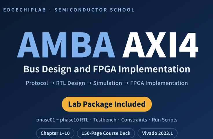
AMBA AXI4 Bus Design and FPGA Implementation — From RTL to System Integration

Learn step by step, from the fundamental principles of the AMBA AXI4 protocol to Verilog RTL design, Vivado simulation verification, and FPGA implementation. Complete a 2-Master × 2-Slave interconnect through single read/write transactions, burst transfers, multi-master arbitration, and address decoding. Furthermore, develop the foundational hardware skills needed to design SoCs that connect RISC-V CPUs with memory, DMA, and peripherals, as well as to port FreeRTOS.

1 learners are taking this course

Level Intermediate

Course period Unlimited

FPGA
FPGA
verilog
verilog
soc
soc
amba
amba
rtl
rtl
FPGA
FPGA
verilog
verilog
soc
soc
amba
amba
rtl
rtl

What you will gain after the course

  • Understand the VALID/READY handshake and five-channel structure of the AXI4 protocol and implement Master/Slave modules in Verilog RTL

  • Designing an AXI Interconnect that connects multiple Masters and Slaves, including address decoding and arbitration logic implementation

  • AXI4-based SoC system integration and verification on an FPGA or simulator

AMBA AXI4 Bus Design and FPGA Implementation — From RTL to System Integration

From understanding the AXI4 protocol to Verilog RTL design, simulation verification, and FPGA implementation! Learn SoC bus and interconnect design through 10 hands-on steps.


How do the CPU, memory, and DMA exchange data?

What happens inside the system when the CPU writes data to or reads data from memory, when the DMA transfers data, or when multiple devices access the same memory simultaneously?

One of the key interfaces that enables these data transfers is AMBA AXI4 (Advanced eXtensible Interface 4).

AXI4 is an interface protocol widely used in SoC (System on Chip) designs to connect various IPs, such as CPUs, DMAs, memories, and hardware accelerators.

However, AXI4 presents several challenges for beginners learning it for the first time.

  • What roles do the five channels—AW, W, B, AR, and R—each play?

  • If VALID and READY are both 1, exactly when is the data transferred?

  • In a burst transfer, how are multiple data items transmitted with a single address request?

  • If the CPU and DMA request the bus simultaneously, who gets to use it first?

  • How do you determine which of the multiple Slaves to send the data to?

  • How can you verify that the designed RTL operates correctly?

This course answers these questions directly by designing RTL and analyzing simulation waveforms.

An AXI4 Design Course That Goes Beyond Theory

This course does not stop at explaining the AXI4 protocol.

Design the AXI Master and Slave in Verilog HDL, and control data transfers through an FSM (Finite State Machine). Then, progressively implement Burst transfers, multi-master arbitration, and address decoding to ultimately build a 2-Master × 2-Slave interconnect system.

In the final stage, you will learn the FPGA implementation and verification process using Vivado.

The key is not only writing the code, but also understanding how the RTL you write operates on each clock cycle.

Analyze FSM state transitions, VALID/READY handshakes, address and data transfers, and response handling by correlating them with simulation waveforms.

Through this, the course is structured to help you understand how AXI4 works from the perspective of actual digital circuits.

Additionally, this course provides the foundation for subsequent learning that integrates RISC-V CPUs, memory, DMA, and peripherals into a single SoC and ports an RTOS such as FreeRTOS.


Learn AXI4 Design Through 4 Sections, 10 Chapters, and 10 Phases

Section 1. AMBA AXI4 Basics and Single Write Transfer

Chapter 1–2 | Phase 1

Understand the basic structure of AXI4 and design a Single Write Transaction in Verilog HDL.

  • The Relationship Between AMBA and AXI4 and the Role of SoC Interconnects

  • The 5 AXI4 channels (AW, W, B, AR, R)

  • VALID/READY Handshake and Data Transfer Conditions

  • AXI Master and BRAM Slave RTL Design

  • FSM State Transitions and Single-Write Transfer Implementation

  • Verifying Write Operations Through Vivado Simulation

Learning Outcome: Understand the basic transfer principles of AXI4 and analyze the RTL and simulation waveforms of a single-write circuit.

Section 2. AXI4 Read and Burst Transfer Design

Chapter 3–5 | Phase 2–5

Expand from single reads to Burst functionality that continuously transfers multiple data items.

  • Single Read Transaction and the AR/R Channels

  • Slave Read Latency and VALID/READY Flow Control

  • Write Burst and Read Burst Transfer Structure

  • Burst length and handling of the last data beat

  • Independent Operation of the Read and Write Channels

  • Verilog FSM Design and Testbench Verification

  • Data Transfer Analysis Using Vivado Waveforms

Learning Outcomes: You will understand the difference between single transfers and burst transfers, and be able to analyze read and write operations using RTL and waveforms.

Section 3. Multi-Master, Arbitration, and Address Decoding

Chapter 6–8 | Phase 6–8

Move beyond a structure connecting a single Master and Slave to design a system in which the CPU and DMA share the bus.

  • Multi-Master System Architecture for CPU and DMA

  • Request/Grant-Based Bus Access Control

  • Arbitration and Bus Arbitration Policy

  • Acquiring and relinquishing bus access using an FSM

  • Slave Selection and Address Decoding Based on Address

  • Address ranges of BRAM and peripherals

  • Distinguishing between bus arbitration and the actual data transfer timing

  • Verification of Multi-Master Operation Through Simulation

Learning Outcomes: Understand how multiple Masters share a bus and analyze the operation of arbitration and address decoding.

Section 4. AXI4 System Integration and FPGA Implementation

Chapter 9–10 | Phase 9–10

Integrate the AXI4 transfers, arbitration, and address decoding learned earlier into a single system.

  • 2-Master × 2-Slave Interconnect Configuration

  • Interconnect Structure Connecting CPU·DMA with BRAM·OLED

  • Integration of Arbitration and Address Decoding

  • Independent transfer paths for the read and write channels

  • Concurrent operation of Masters accessing different Slaves

  • RTL and Simulation Verification of the Integrated System

  • Connecting the FPGA Top Module and Submodules

  • Vivado synthesis, implementation, and bitstream generation

  • FPGA board-based system operation verification

Learning outcomes: You will understand the integrated structure of the AXI4 interconnect and gain experience with the design process from simulation verification through FPGA implementation.


Features Unique to This Course

1. Learn step by step, from single transfers to system integration

We do not present a complex AXI4 interconnect from the outset.

Starting with single writes and reads, you will sequentially learn Burst transfers, Multi-Master, Arbitration, and Address Decoding.

Each stage is structured so that the concepts learned lead into the design of the next stage.

2. Learning Centered on FSMs and Simulation Waveforms

AXI4 is difficult to understand by simply memorizing the names of its signals.

In this course, we explain the connection between FSM state transitions and the clock cycles in which actual handshakes are established.

Through this, you can verify the order and conditions under which address requests, data transfers, and response processing take place.

3. Hands-on Practice Based on Verilog RTL

Using the provided Verilog RTL and testbench, you will learn how each phase operates.

Learn how to perform simulations in Vivado and verify circuit functionality through waveforms.

Beyond simply explaining protocol concepts, the focus is on understanding actual RTL design structures.

4. A System Perspective Connected to Actual SoC Design

Learn the need for bus arbitration and address decoding through an educational interconnect that connects the CPU and DMA, as well as BRAM and OLED.

This provides a foundation for understanding system design that connects various hardware IPs, such as RISC-V CPUs, DMA Controllers, NPUs, and memory controllers.

5. A Design Flow Extending Through FPGA Implementation

Learning does not end with writing and simulating RTL.

Explore the flow of implementing RTL as actual hardware through synthesis, implementation, bitstream generation, and FPGA board verification using Vivado.

6. A Foundational Course Leading to RISC-V SoC and RTOS-Based System Design

This course lays the foundation for hardware system design needed to connect a RISC-V CPU with various peripherals, such as memory, DMA, sensors, and displays, and to port an RTOS (Real-Time Operating System) in the future.

Designing a RISC-V CPU alone is not enough to build a complete embedded system. You need to understand bus interfaces, address decoding, data transfer, and interconnect structures so that the CPU can access memory and peripherals.

The AXI4 design skills learned in this course provide foundational knowledge that can later be used for RISC-V-based SoC integration, memory-mapped peripheral control, and building interrupt and RTOS execution environments.

This is a foundational course designed to expand learning from AXI4 bus design to RISC-V SoC integration and embedded system development using an RTOS such as FreeRTOS.


Competencies Gained After Completing the Course

By the end of this course, you will be expected to have the following competencies.

  1. Understanding the AXI4 Protocol: You can explain the roles of the five channels and the VALID/READY handshake.

  2. RTL Design and Analysis: Understand the structure of AXI Master/Slave and FSMs, and analyze transfer operations.

  3. Understanding Burst Transfers: You can explain continuous data transfers and completion conditions.

  4. Interconnect Design: You can understand the operation of Multi-Master Arbitration and Address Decoding.

  5. Simulation Verification: You can verify RTL behavior using Vivado testbenches and waveforms.

  6. FPGA Implementation: You can understand the FPGA integration and implementation flow of an AXI4-based system.

  7. Preparation for Subsequent System Design: You can understand the SoC architecture that connects a RISC-V CPU with peripherals and acquire the hardware foundation needed for future RTOS porting.

Recommended for those who:

  • Electrical engineering and semiconductor engineering students: Those who want to systematically learn AXI4 and SoC interface design

  • Verilog HDL learners: Those who want to expand from basic digital circuit design to bus and system design

  • FPGA·RTL Design Engineers: Those who want to understand the internal operation of AXI4 and interconnect structures

  • Beginners in CPU, NPU, and SoC development: Those who want to learn the interconnection structure of CPUs, DMAs, memory, and hardware accelerators

  • RISC-V and RTOS learners: Those who want to understand the connection structure between the CPU and peripherals and later expand their learning into FreeRTOS-based embedded system design

Prerequisite Knowledge and Hands-On Environment

Recommended Prerequisite Knowledge

  • Basic Concepts of Digital Logic Circuits

  • Basic syntax of Verilog HDL

  • Basic understanding of clock-based sequential circuits and FSMs

  • Experience using Vivado will be helpful for learning.

Lab Environment

  • HDL: Verilog

  • Development Tool: AMD Vivado 2023.1

  • Lab materials: Step-by-step RTL, testbenches, and execution scripts

  • Lab method: Vivado simulation and FPGA implementation

  • FPGA Lab: Based on the Boards and Constraint Files Used in the Course

Lecture Materials and Learning Guide

This course is based on a total of 150 pages of lecture materials and progressively explains AXI4 design principles across 4 sections and 10 chapters.

The RTL for the exercises, testbenches, and execution scripts are provided through the resource repository introduced in the course.

Each Phase’s exercises are conducted based on the provided files, and the internal verification performed during the development of the textbook is distinguished from the exercises run directly by students.

Course Scope Overview

This course does not implement every feature of the full AMBA AXI4 specification. It uses an educational subset to help you understand AXI4’s core operating principles and explains the distinction between implemented and unsupported features.

Furthermore, RISC-V SoC integration and FreeRTOS porting are not implemented directly in this course; rather, they are areas for further study that can be developed using the AXI4 design knowledge acquired in this course.


From AXI4 to RISC-V SoCs and RTOS-Based System Design

In this course, you will start by understanding the basic signals and protocol of AXI4, then learn Verilog RTL design, simulation verification, multi-master interconnect configuration, and FPGA implementation.

Furthermore, this lays the foundation for advanced study, integrating a RISC-V CPU, memory, DMA, and peripherals into a single SoC and porting an RTOS such as FreeRTOS.

Starting with AXI4 bus design, broaden your learning to include embedded system design in which the CPU and peripherals work together.

Recommended for
these people

Who is this course right for?

  • Electrical engineering students who know the basics of Verilog and are looking to enter FPGA or ASIC design

  • An RTL design beginner with digital circuit design experience who is learning system bus interfaces for the first time

  • Semiconductor design engineer preparing to develop SoC components such as RISC-V CPUs, NPUs, and memory controllers

Need to know before starting?

  • Experience with basic Verilog HDL syntax and combinational and sequential circuit design

  • Understanding the concepts of registers and FSMs (finite-state machines) in digital logic circuits

  • Experience using simulation tools (ModelSim, Vivado, etc.) or FPGA development environments

Hello
This is EdgeChipLab

Career Verified

"In the AI era, the surest response is to build AI semiconductors yourself."

This program is neither a theory-focused university course nor the standardized curriculum of a contract department tailored to specific specifications. Nor is it limited to simply gaining experience using EDA tools or leveraging libraries, as in conventional fragmented practical seminars.

It is a one-of-a-kind, hands-on course designed and FPGA-validated by a practicing engineering professor with 30 years of experience, who began as a systems semiconductor researcher in Samsung Electronics’ DS Division, won the Silver Prize (Group Chairman’s Award) at the Samsung Technology Awards in the field of design automation, and went on to serve as a Director at Samsung’s UK and German subsidiaries and as the head of the System LSI Marketing and Sales Group.

[ Key differentiators for working professionals & aspiring engineers ]

  • Overcome the limitations of working engineers: Go beyond simply modifying code or using off-the-shelf IP to acquire practical, architecture-level expertise in designing NPUs and CPUs directly in RTL.

  • Establishing a Full-Flow practical system: Complete the entire value chain, from analyzing AI algorithms to FPGA implementation and Bit-True hardware integration verification, and extending to an AI SoC based on a CPU + NPU + RTOS.

  • Field validation complete: Going beyond theory taught in university classrooms, we deliver proven processes that can be applied immediately in real-world work, distilling design expertise from the front lines of industry.

AI Algorithm → RTL Design → FPGA Implementation → Bit-True Verification → AI SoC

For undergraduates and graduate students, as well as working professionals seeking to advance as next-generation AI semiconductor/SoC designers, it provides an unparalleled, top-tier practical guide.


Beyond theory to actual AI hardware implementation

It is difficult to develop system-level AI semiconductor design capabilities with only scattered, fragmented knowledge.

Students do not stop at using completed black-box IP. The goal is to progressively develop the system design skills needed to design an AI NPU and RISC-V CPU themselves, integrate memory and peripherals, port an RTOS on top of them, and ultimately build their own AI SoC.

Starting with the fundamentals of transistors and digital circuits, this course connects FPGA, CPU, and NPU technologies to hardware for accelerating Transformers and LLMs.


We validate the research results on actual FPGA hardware.

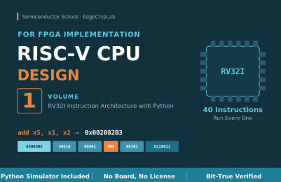
This is not a lecture you only watch. Rather than stopping at theory or simple simulations, you will run AI semiconductor circuits you designed yourself on an actual FPGA and perform Bit-True verification, confirming that the Python model and RTL results match down to the last bit.

The instructor also connects research results, including four KCI-indexed papers on AI semiconductors, FPGAs, and RISC-V, to the educational content, taking technologies validated through research into actual design and FPGA implementation. The source code needed for the exercises—including a self-developed RISC-V CPU, Python code for image training, and Verilog RTL—is made available.

Built around the affordable Arty S7-25 FPGA board and the free Vivado design tool, this course enables learners to reproduce the entire process of designing, implementing, and verifying their own work. It can also be used with Digilent FPGA boards, including the Zybo Z7. Simply modify the XDC pin mapping (board) and clock division parameters (RTL) to match your board. The 'MNIST NPU with FPGA' course only requires modifying the XDC pin mapping, while courses that use an OLED and camera require modifying the clock division parameters (RTL).

→The lecture exercises are configured with divider parameters based on Arty S7’s 100 MHz input clock. Since other boards have different input clocks (e.g., Zybo Z7 uses 125 MHz), you will need to recalculate the divider values so that the target frequency remains the same. If you overlook this, the screen or video may not display properly,so please check, as it can easily be mistaken for a code error.


A seamless full-stack roadmap: from the basics to a mini LLM accelerator

Every lecture is not an isolated fragment, but part of a journey toward completing one vast system.

  • Step 1: AI Theory and Image Processing Fundamentals (including Machine Learning)

  • Step 2: AI Accelerator (NPU) Design and Verification (Including Machine Learning)

  • Step 3: RISC-V CPU Design and System Integration

  • Step 4: Advanced AI SoC Implementation and Expansion into a mini LLM Acceleration Platform (Continuous Content Updates)


Objective verification metrics

All design deliverables from this course have undergone rigorous validation against global standards and by the academic community.

  • RISC-V Architecture Verification: In-house developed RISC-V CPU, passed the International Foundation’s official compliance test (ACT), and source code released (GitHub)

  • Academic Authority: Four Sole-Author Academic Papers (published in the prestigious KCI A-ranked journal IJIBC)

  • Global Recognition: Published four global Amazon technology books (reached #1 bestseller status)


    Published books: Roger Kim: books, biography, latest update

  • Real-World Operation Verification Complete: Core IPs, including the RV32I CPU, NPU, vision system, GPS, Transformer, and AURA-Edge SoC, operate flawlessly in the Arty S7 environment.


Take on the challenge. By the time you complete this process of uploading code to the board yourself and checking the results, you will have leveled up into a hardware engineer with a completely different perspective than before.

More

Curriculum

All

4 lectures ∙ (2hr 25min)

Published: 
Last updated: 

Reviews

Not enough reviews.
Please write a valuable review that helps everyone!

EdgeChipLab's other courses

Check out other courses by the instructor!

Similar courses

Explore other courses in the same field!

Limited time deal

$6,096.00

29%

$52.80