inflearn logo

Introduction to FSM Design | From State Diagrams to Verilog-HDL 3-Process Implementation

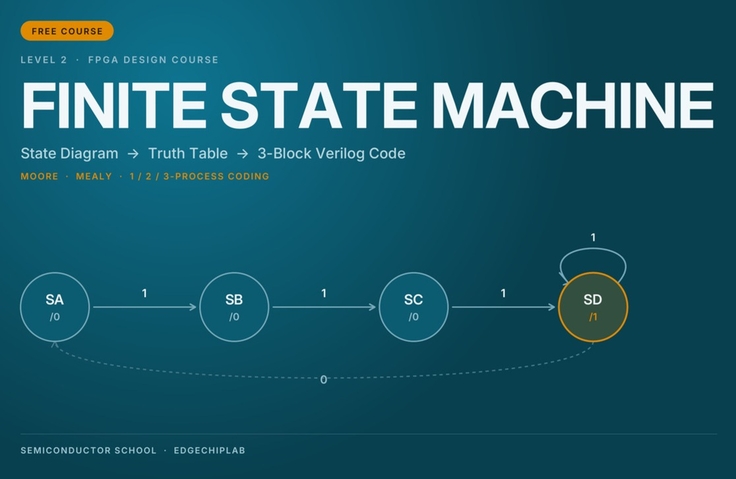
This free course provides a systematic introduction to FSM (Finite State Machine) design, a core component of digital semiconductor control circuits. Through a Pattern Detector example, you will learn the practical design process step by step, including comparisons of Moore and Mealy architectures, creating State Diagrams, deriving Truth Tables, and 3-Process Coding in Verilog-HDL. Establish the essential foundational theory for digital hardware design, including FPGA, RISC-V CPUs, and AI NPUs.

8 learners are taking this course

Level Beginner

Course period Unlimited

verilog
verilog
diagram
diagram
digital-logic
digital-logic
context-switching
context-switching
rtl
rtl
verilog
verilog
diagram
diagram
digital-logic
digital-logic
context-switching
context-switching
rtl
rtl
Thumbnail

What you will gain after the course

  • FSM State Diagram Design and Criteria for Choosing a Moore/Mealy Architecture

  • A systematic design process for converting a state diagram into Verilog-HDL 3-process code via a truth table

  • Stable RTL Coding Principles Including Latch Prevention and the Use of Output Registers

Introduction to FSM Design | From State Diagrams to Verilog-HDL 3-Process Implementation

How do you design control circuits for digital semiconductors?

From traffic lights, vending machines, and communication controllers to CPUs and AI NPUs, various digital systems operate according to predetermined conditions and sequences.

The key technology for systematically designing these sequential operations is FSM (Finite State Machine).

This course is a free FSM design theory course that covers everything from the basic concepts of FSMs to Moore and Mealy architectures, State Diagrams, Truth Tables, and 3-Process Coding in Verilog-HDL.

Rather than simply memorizing FSM code, the focus is on understanding the design process that progresses from state diagrams → truth tables → RTL code.


What you will learn in this course

Section 1. Basic Concepts and Structure of FSMs

Learn what an FSM is and what role it plays in digital circuits.

  • Difference Between Combinational and Sequential Circuits

  • Basic Structure of an FSM and State Registers

  • Concepts of State and State Transition

  • Components of a State Diagram

  • State Definition and State Encoding Using the Pattern Detector 111

Learning point: Understand how to represent the behavior of digital systems using states and transition conditions.


Section 2. Moore and Mealy FSM

Compare the two representative FSM structures and examine which structure to choose depending on the design objectives.

  • Structure and Operating Principles of a Moore Machine

  • Structure and Operating Principles of a Mealy Machine

  • Differences in Output Timing and Glitches

  • Timing Closure and Output Stability

  • Trade-off Between the Number of States and Response Speed

  • Hybrid Architecture Using an Output Register

Learning Point: Understand the difference between Moore and Mealy machines and learn the considerations for actual hardware design.


Section 3. FSM Design and Verilog-HDL Implementation

Learn the process of designing an FSM and expressing it in Verilog-HDL code using the Pattern Detector 111 example.

  • Creating a State Diagram

  • Next-State Truth Table and Output Truth Table

  • State Register, Next-State Logic, Output Logic

  • Verilog-HDL 3-Process Coding

  • Comparison of 1-Process, 2-Process, and 3-Process Structures

  • Causes of Latch Inference and How to Prevent It

  • Output Glitches and Output Registers

  • Core Principles of FSM Design

Learning Point: Understand how to systematically write RTL code for an FSM based on state diagrams and truth tables.


What you will gain from this course

  1. Understanding FSM Structure and Operating Principles
    Understand the concepts of states and state transitions, and learn to represent the control operations of digital systems using a State Diagram.

  2. Understanding the Differences Between Moore and Mealy Architectures
    You will be able to compare output methods, response speed, glitches, and timing characteristics, and explain the considerations for design.

  3. Learn the design process from state diagrams to RTL code
    Learn how to create a State Diagram and Truth Table and translate them into Verilog-HDL's 3-Process structure.

  4. Learn proper FSM coding principles
    Understand the differences between 1-, 2-, and 3-Process Coding Styles and learn basic principles for preventing major design issues such as latches and output glitches.


Recommended for

  • Those who want to learn FSM design after learning the basic syntax of Verilog-HDL

  • University students and beginners interested in FPGA design and digital control circuit implementation

  • Those who want to learn how to convert State Diagrams and Truth Tables into RTL code

  • Those who want to clearly understand the difference between Moore and Mealy FSMs

  • Those preparing to design control circuits for RISC-V CPUs, AI NPUs, and SoCs.


Why should you learn FSMs?

In digital hardware design, control circuits are just as important as computational circuits.

When should data be read, when should computation begin, and how can we determine whether the result is ready?

FSMs are used to manage these sequences of operations.

In particular, FPGA, CPU, NPU, and communication controllers must perform multiple operations in a prescribed sequence, so the ability to clearly define states and transition conditions is essential.

In this course, we explain the entire FSM design process through a simple example called Pattern Detector 111.

By connecting a single example through its state diagram, truth table, and Verilog-HDL code, this course is structured to help you systematically understand FSM design methods.


Course Information

This course is a free foundational course from Semiconductor School | EdgeChipLab.

If you have basic knowledge of Verilog-HDL Modules, Always blocks, If/Case statements, and combinational and sequential logic, you will find this course easier to follow. If you need prerequisite learning, please take the free course “Introduction to Verilog-HDL for Digital Semiconductor Design” first.

This course explains FSM design theory and RTL code structure. Actual Verilog-HDL coding, Vivado simulation, and FPGA implementation are covered in the subsequent hands-on course.

Go beyond simply understanding the concept of FSMs and learn the design thinking needed to connect state diagrams to truth tables and truth tables to RTL code.

Semiconductor School | EdgeChipLab

Recommended for
these people

Who is this course right for?

  • College students and beginners who want to learn the basics of Verilog-HDL syntax and expand into FSM design

  • Learners preparing to implement FPGAs and digital control circuits

  • Engineers interested in designing RISC-V CPUs, AI NPUs, and SoC control circuits

Need to know before starting?

  • Concepts of Combinational and Sequential Logic in Digital Logic Circuits

  • Basic Operating Principles of Flip-Flops and Clocks

  • Verilog-HDL Module, Always, and If/Case Syntax Basics

Hello
This is EdgeChipLab

Career Verified

"In the AI era, the surest response is to build AI semiconductors yourself."

This program is neither a theory-focused university course nor the standardized curriculum of a contract department tailored to specific specifications. Nor is it limited to simply gaining experience using EDA tools or leveraging libraries, as in conventional fragmented practical seminars.

It is a one-of-a-kind, hands-on course designed and FPGA-validated by a practicing engineering professor with 30 years of experience, who began as a systems semiconductor researcher in Samsung Electronics’ DS Division, won the Silver Prize (Group Chairman’s Award) at the Samsung Technology Awards in the field of design automation, and went on to serve as a Director at Samsung’s UK and German subsidiaries and as the head of the System LSI Marketing and Sales Group.

[ Key differentiators for working professionals & aspiring engineers ]

  • Overcome the limitations of working engineers: Go beyond simply modifying code or using off-the-shelf IP to acquire practical, architecture-level expertise in designing NPUs and CPUs directly in RTL.

  • Establishing a Full-Flow practical system: Complete the entire value chain, from analyzing AI algorithms to FPGA implementation and Bit-True hardware integration verification, and extending to an AI SoC based on a CPU + NPU + RTOS.

  • Field validation complete: Going beyond theory taught in university classrooms, we deliver proven processes that can be applied immediately in real-world work, distilling design expertise from the front lines of industry.

AI Algorithm → RTL Design → FPGA Implementation → Bit-True Verification → AI SoC

For undergraduates and graduate students, as well as working professionals seeking to advance as next-generation AI semiconductor/SoC designers, it provides an unparalleled, top-tier practical guide.


Beyond theory to actual AI hardware implementation

It is difficult to develop system-level AI semiconductor design capabilities with only scattered, fragmented knowledge.

Students do not stop at using completed black-box IP. The goal is to progressively develop the system design skills needed to design an AI NPU and RISC-V CPU themselves, integrate memory and peripherals, port an RTOS on top of them, and ultimately build their own AI SoC.

Starting with the fundamentals of transistors and digital circuits, this course connects FPGA, CPU, and NPU technologies to hardware for accelerating Transformers and LLMs.


We validate the research results on actual FPGA hardware.

This is not a lecture you only watch. Rather than stopping at theory or simple simulations, you will run AI semiconductor circuits you designed yourself on an actual FPGA and perform Bit-True verification, confirming that the Python model and RTL results match down to the last bit.

The instructor also connects research results, including four KCI-indexed papers on AI semiconductors, FPGAs, and RISC-V, to the educational content, taking technologies validated through research into actual design and FPGA implementation. The source code needed for the exercises—including a self-developed RISC-V CPU, Python code for image training, and Verilog RTL—is made available.

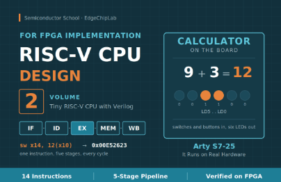
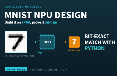
Built around the affordable Arty S7-25 FPGA board and the free Vivado design tool, this course enables learners to reproduce the entire process of designing, implementing, and verifying their own work. It can also be used with Digilent FPGA boards, including the Zybo Z7. Simply modify the XDC pin mapping (board) and clock division parameters (RTL) to match your board. The 'MNIST NPU with FPGA' course only requires modifying the XDC pin mapping, while courses that use an OLED and camera require modifying the clock division parameters (RTL).

→The lecture exercises are configured with divider parameters based on Arty S7’s 100 MHz input clock. Since other boards have different input clocks (e.g., Zybo Z7 uses 125 MHz), you will need to recalculate the divider values so that the target frequency remains the same. If you overlook this, the screen or video may not display properly,so please check, as it can easily be mistaken for a code error.


A seamless full-stack roadmap: from the basics to a mini LLM accelerator

Every lecture is not an isolated fragment, but part of a journey toward completing one vast system.

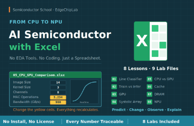
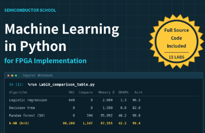
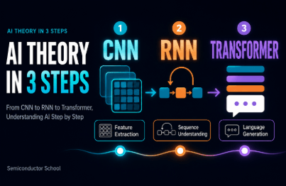
  • Step 1: AI Theory and Image Processing Fundamentals (including Machine Learning)

  • Step 2: AI Accelerator (NPU) Design and Verification (Including Machine Learning)

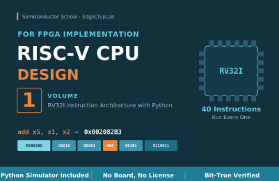
  • Step 3: RISC-V CPU Design and System Integration

  • Step 4: Advanced AI SoC Implementation and Expansion into a mini LLM Acceleration Platform (Continuous Content Updates)


Objective verification metrics

All design deliverables from this course have undergone rigorous validation against global standards and by the academic community.

  • RISC-V Architecture Verification: In-house developed RISC-V CPU, passed the International Foundation’s official compliance test (ACT), and source code released (GitHub)

  • Academic Authority: Four Sole-Author Academic Papers (published in the prestigious KCI A-ranked journal IJIBC)

  • Global Recognition: Published four global Amazon technology books (reached #1 bestseller status)


    Published books: Roger Kim: books, biography, latest update

  • Real-World Operation Verification Complete: Core IPs, including the RV32I CPU, NPU, vision system, GPS, Transformer, and AURA-Edge SoC, operate flawlessly in the Arty S7 environment.


Take on the challenge. By the time you complete this process of uploading code to the board yourself and checking the results, you will have leveled up into a hardware engineer with a completely different perspective than before.

More

Curriculum

All

3 lectures ∙ (23min)

Published: 
Last updated: 

Reviews

Not enough reviews.
Please write a valuable review that helps everyone!

EdgeChipLab's other courses

Check out other courses by the instructor!

Similar courses

Explore other courses in the same field!

Free