STM32 FreeRTOS Implementation
alex
We will explain in detail how to implement FreeRTOS on STM32 MCU.
Basic
FreeRTOS
In this course, students will learn how to implement Verilog using the Zynq board.
Reviews from Early Learners
5.0
권홍근
Hello, I'm a student who recently purchased your course. I'm writing because I'm not sure how to utilize the course materials. Is my coding skills improving by just typing in the source code and questioning why it was coded that way? I would be very grateful if you could provide me with a specific learning method.
5.0
박현영
It's harder than I thought to find an FPGA design lecture, but this is a fun lecture that I can follow along step by step while looking at the textbook!!! In addition to this lecture, please make many, many other lectures that utilize the Zynq board~!! I want to upgrade my skills by taking all of them, gaining experience, and practicing. Thank you~!
5.0
draco
It helped me with my coding style.
Verilog coding
Utilizing ZYNQ Board
How to use Vivado, Vitis
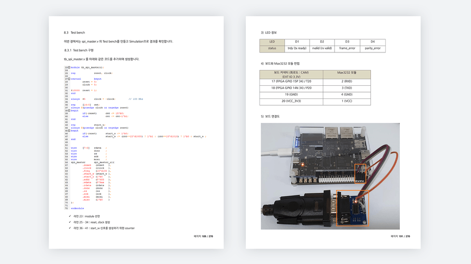
Create a Test Bench and Verify Simulation
Download to board and check results
The core of implementing and practicing using the Zynq board.
📢 Please note before taking the class.
✅ Code implementation ✅ Simulation verification using Text Bench ✅ Board verification
Before coding, we analyze the overall system and provide know-how on how to code efficiently. We provide easy-to-understand explanations based on extensive techniques and know-how gained from over 20 years of field experience. Furthermore, the source code included in the lectures is not for study purposes but rather is used in real-world applications. All attendees will receive access to the full source code used in the lectures.
The first half of the lecture will cover the following two topics:
In the latter part of the lecture , we will verify the results downloaded to the board through coding and simulation verification for each topic.
Q. Who is the target audience for this lecture?
This course is designed for those interested in learning Verilog and FPGAs. This course restructures the "Using FPGAs with Verilog" section to enable implementation on the Zynq board. All source code is verified on the Zynq mini 7020 (7010) board.
Q. Is there anything I need to prepare to attend the lecture?
All of the lecture content can be practiced on the Zynq mini 7020 (7010) board. Having a Zynq mini 7020 (7010) board available will be very helpful, as you can implement the code yourself and verify the results.
Q. What program tools do you use?
I'm using Vivado version 2022.1. The lecture includes instructions on installing tools, so please follow the instructions to install them.
Q. Where can I buy the Zynq mini board?
You can purchase it through domestic shopping malls or AliExpress.
I've worked as a developer for over 20 years at both large and small companies, and I currently run a small business. I've developed an ISP (Image Signal Processing) ASIC for CCTV, and I've developed numerous FPGA-based products, including OLED inspection equipment and DAQ (Data Acquisition System). Beyond FPGAs, I have extensive experience in software development (STM32, PIC32, AVR, ATMEGA, etc.), circuit design, and Windows programming.
💾 Please check the lecture environment.
Who is this course right for?
For those who want to learn FPGA
For those who want to learn Verilog
For those who want to learn Zynq
Need to know before starting?
C language
Verilog Language (Basics)
1,725
Learners
87
Reviews
130
Answers
4.8
Rating
17
Courses
I have worked as a developer at both large corporations and SMEs for the past 20 years,
I am currently the CEO of a small company.
Key career highlights include
FPGA design using Verilog HDL
ISP ASIC development for CCTV (approx. 10 years)
OLED Display inspection equipment development (approx. 3 years)
Equipment development using FPGA
MCU FW
STM32
PIC32
AVR, ATMEGA
DSP (TI)
Windows Application Development
Visual Studio MFC, C++
.
All
381 lectures
Course Materials:
All
4 reviews
5.0
4 reviews
Reviews 5
∙
Average Rating 5.0
5
It's harder than I thought to find an FPGA design lecture, but this is a fun lecture that I can follow along step by step while looking at the textbook!!! In addition to this lecture, please make many, many other lectures that utilize the Zynq board~!! I want to upgrade my skills by taking all of them, gaining experience, and practicing. Thank you~!
Thank you for your review. I worked hard to make it, so this kind of review is a great help. Verilog and FPGA are not easy to learn. However, if you learn step by step, your skills will gradually improve and you will gain confidence. I hope you will become a capable developer through the lecture. Thank you ~!!
Reviews 1
∙
Average Rating 5.0
5
Hello, I'm a student who recently purchased your course. I'm writing because I'm not sure how to utilize the course materials. Is my coding skills improving by just typing in the source code and questioning why it was coded that way? I would be very grateful if you could provide me with a specific learning method.
Hello, Learning Verilog and FPGA is very different from learning higher-level languages (C, App, Java, etc.). Verilog and FPGA are closely related to hardware. It's about designing the hardware itself. For example, if you think about UART communication, in the upper Application layer, you create a serial protocol and implement communication. In the FPGA layer, you design and implement the UART Controller itself. What is implemented in the FPGA layer is implemented in Main Clock units. It's about implementing how signals are implemented for each clock. In the Application, you implement code at the Protocol level. To study Verilog and FPGA, it may not be very meaningful to do it simply for study purposes. The best way is to learn basic functions (you need to learn to implement code as you like and use tools) and implement something new while doing real projects. You can think of this lecture as learning the prerequisite technologies for proceeding with real projects. To do a real project, it is very important to handle Verilog, FPGA, tools, etc. freely. You need to familiarize yourself with the process of coding with Verilog, verifying with simulation (if there is an error, modify the code and verify with simulation again), and checking the operation by uploading the implemented content to the board. If you are somewhat familiar with the contents of this lecture, you can proceed with projects from small things in actual practice. A recent project I worked on was implementing a Frame Converter (DDR3) in an FPGA to output image data coming from a PC via USB to LVDS. To implement these things, you need the contents of this lecture, implement DDR3 Controller, and understand LVDS. Anyway, learning Verilog and FPGA is not easy. However, I believe that if you learn the basic functions well and acquire various technologies while working on projects in the field, you will become a good developer. Please learn with patience. Thank you.
First of all, thank you so much for the detailed reply. As I take the lectures, if I have any questions or get stuck, would it be okay to ask questions here? If there is a more convenient way to contact you, such as by email, please let me know.
You can send it via email or post your question on the cafe I run. Email: alex@ihil.co.kr Cafe: Cafe.naver.com/worshippt Thank you.
Okay, I understand. Have a great day today. Thank you.
Reviews 5
∙
Average Rating 5.0
5
It helped me with my coding style.
Thank you for helping me with my coding style. I think it is very important for developers to develop their own coding style. I think that using SM(State Machine) in algorithm development is very important and useful as time goes by. I recommend you to use SM a lot. Thank you ~!!
Reviews 1
∙
Average Rating 5.0
Check out other courses by the instructor!
Explore other courses in the same field!
$84.70