
STM32 CAN通信
ihil
STM32 MCUを使用してCAN通信を実装する方法を説明するテキスト形式のレッスンです。
Basic
CAN, MCU
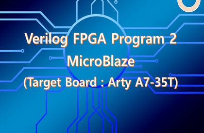
Learn how to implement MicroBlaze on Xilinx FPGA.
Using MicroBlaze in FPGA
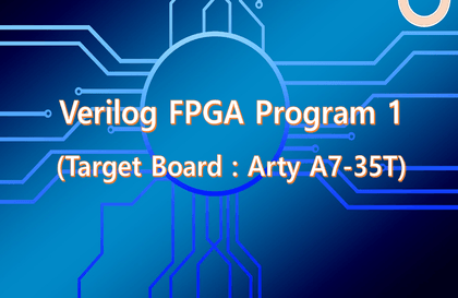
Verilog program
FPGA programming
MicroBlaze is a processor offered in IP form on an FPGA. MicroBlaze separates the processor core from the peripherals, allowing users to configure the peripherals to suit their specific needs.
Verilog HDL is an FPGA programming language. It can be used to create not only FPGAs but also ASICs. Many developers are interested in Verilog or want to improve their skills in the field.
However, Verilog and FPGAs are very specialized fields, so finding a course that explains them in detail is very difficult. FPGA manufacturers provide documentation, but so many of them are in English that it's hard to know which ones to refer to.
I've worked as a developer in the industry for over 20 years and currently run a one-person business. I created this course to share the knowledge I've accumulated with those who are already working as developers or preparing for a career in the field.
The lecture consists of a total of 4 parts.
This lecture, the second in a series, covers MicroBlaze. MicroBlaze is a 32-bit microprocessor from Xilinx. Using MicroBlaze, you can simultaneously implement processors and user logic within an FPGA. Furthermore, by implementing an interface between the processor and user logic, you can create a system-on-chip (SOC) within the FPGA. This lecture is designed to be easy to follow, even for beginners. It covers tool installation and usage, code explanation, code simulation, and verification of results on a development board.
Becoming a competent developer is no easy task. It requires a lot of effort. It's a great help to have Kind Guide in this difficult process.
This course covers a lot of material. Unless you're an experienced developer, it may be difficult to grasp everything in one sitting. By repeatedly coding, simulating, and checking the results on the board, you'll gradually be able to internalize it.
If you can fully understand and utilize the contents of this lecture, you can become a very good developer.
If there is anything you do not understand in the lecture, please post a question through the Inflearn community or the cafe I run , and I will answer it.
📢 Please make sure to check before taking the class!
This course is a text lecture in electronic format. All source files used in the lecture will be provided to those who take the course. The course will be produced as a video in the future.
This lecture is based on Vitis 2022.1, the version after 2019.
The board used in this course's practical exercises is the HIL-A35T, developed by our company for this purpose. It can be purchased from our company's Smart Store (Smart Store Link: https://smartstore.naver.com/ihil).
Lecture materials can be downloaded from 'Section 0 - Material Sharing Link - Attachments'.
Lecture 1: Verilog FPGA Program 1
Implementing basic functions
Lecture 2: Verilog FPGA Program 2
Microblaze
Lecture 3: Verilog FPGA Program 3
DDR Controller
Lecture 4: Verilog FPGA Program 4
MCU Porting
Basics: Fundamentals of FPGA Utilization Using Verilog
Arty A7-35T board (Digilent)
Verilog FPGA Program 1 (Arty A7-35T)
Verilog FPGA Program 2 (MicroBlaze1, Arty A7-35T)
Verilog FPGA Program 2 (MicroBlaze2, Arty A7-35T)
Verilog FPGA Program 3 (DDR Controller, Arty A7-35T)
Verilog FPGA Program 4 (MCU Porting, Arty A7-35T)
Zynq mini 7020 board
Verilog FPGA Program 1 (Zynq mini 7020)
Verilog ZYNQ Program1 (Zynq mini 7020)
HIL-A35T board (developed in-house for lectures)
Verilog FPGA Program 1 (HIL-A35T)
Verilog FPGA Program 2 (MicroBlaze, HIL-A35T)
Verilog FPGA Program 3 (DDR Controller, HIL-A35T)
Verilog FPGA Program 4 (MCU Porting, HIL-A35T)
The lecture content is
Immediately applicable to practical use!
Tested and proven
Open source provided!
Debugging, development required
Windows app program provided!
Section 1. HW Configuration
Section 2. Vitis 2022.1 Installation Process
Vitis is a very heavy tool. We explain what to be careful about when installing it and how to install it without interfering with your current Vivado installation.
Section 3. Print “Hello world” on the screen with MicroBlaze
This section aims to provide a general overview of the process.
Section 4. Peripheral of MicoBlaze
This course covers the most commonly used GPIO, Timer, UART, and Interrupt. Since the peripherals provided by MicroBlaze are similar, once you master the course content, you'll be able to easily use other peripherals.
Section 5. Knowledge Applicable to Practice
Most materials end with dealing with peripherals. However, the purpose of using MicroBlaze in an FPGA is to control user-designed logic through MicroBlaze. Ultimately, the goal is to control user-designed logic through a user interface (UI).
In this lecture, we added four PWM modules to configure user logic. We configured a register map to control the user logic, and controlled the user logic through MicroBlaze and the UI. We explained and implemented the entire process, and presented the results.
The content described in this section is immediately applicable to your practice. Simply add User Logic and a Register Map, and all other steps can be implemented as is.
Section 6. lwIP Echo Server
This section describes how to implement an Echo Server using lwIP. Implement a DDR Controller to use cache (instruction cache, data cache) in MicroBlaze.
Section 7. Leveraging lwIP
This section describes the process of adding user logic to TCP/IP communication using lwIP. This section describes the process of sending commands via TCP/IP from a PC, receiving them via lwIP, and controlling the board's LEDs via user logic. Through this process, we'll implement the interface between lwIP and user logic and verify the results.
Section 8. TCP/IP Implementation Using the W5500 Module
This was added in v1.4. This tutorial demonstrates TCP/IP implementation using Wiznet's w5500 module. It connects a PC to a network and enables data transmission and reception. This approach can be applied to a variety of fields that utilize TCP/IP.
Section 9. Block Memory Interface - 1
Added in v1.5. Implements the Block Memory Interface provided by default in Block Design.
Section 10. Block Memory Interface - 2
This is what was added in v1.5. We implemented the Block Memory Interface by adding Block Memory to User Logic. We apply this to implement the User Register Map and implement an example that controls the PWM frequency and duty cycle.
Section 11. Implementing the w5500 Interface
Implement TCP/IP communication using the w5500 module.
Who is this course right for?
If you are interested in MicroBlaze
If you are interested in FPGA
Anyone interested in Verilog
Need to know before starting?
C language
Verilog HDL
Xilinx FPGA
1,647
Learners
66
Reviews
123
Answers
4.8
Rating
19
Courses
저는 지난 20여년 동안 대기업, 중소기업에서 개발자로 일해왔고
현재는 작은 기업의 대표로 있습니다.
주요 경력사항은
Verilog HDL을 이용한 FPGA 설계
CCTV용 ISP ASIC 개발 (약 10년)
OLED Display 검사장비 개발 (약 3년)
FPGA를 이용한 장비 개발
MCU FW
STM32
PIC32
AVR, ATMEGA
DSP (TI)
Windows Application Program
Visual Studio MFC, C++
입니다.
All
358 lectures
Course Materials:
$84.70
Check out other courses by the instructor!
Explore other courses in the same field!